Babylon The Ring City

To: The Leaders of the G20 Nations [and their ministries]
Copies to: the worlds media corporation

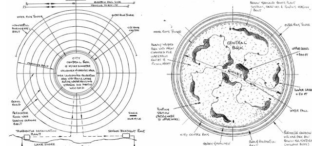
In order to eliminate urban sprawl and to avoid the use of personal transportation from all areas of the “Ring City“, we can, by integrating all residences, schools ,colleges, universities, hospitals, medical centers, shopping malls, fitness centers, sports fields, sports stadiums, entertainment centers, museums, galleries, into that city ring [ of some 7 miles diameter], create a magnificent city structure that is fully serviced and provides a vibrant and enriched lifestyle for everyone.

Within the city ring [with an inner diameter of 6 miles and an outer diameter of about 6.8 miles] and between the inner and outer residential ring towers, there will be a continuous belts of land escaped gardens and recreational park with a total area of about 5 sq.miles. The approximate population of the city [with each of the ring tower residences having some 80 floors and a total compliment of apartments [of various sizes] of about 1,600,000] would be about 3,000,000.

A central park [a wilderness area with many lakes, waterfalls, rapids, streams and trails for hiking and biking] with a diameter of 6 miles, would provide a further city parkland of some 28 sq. miles for the enjoyment of the residents.

The ring city would be provided with a subway system [operating 24 hours a day] running under the massive circular structure and a separate subway link serving the airport [and linking with national electric rail and bus services], that would be free for all residents so that every part of the many and varied facilities would be minutes away for any resident.

A four level visitors car and coach park [electric vehicles only] would be provided adjacent to the outer perimeter of the outer circle tower and will accommodate all daily visitors travelling by car at a reasonable daily charge. Within this car and coach park belt will be electric car rentals so that city residents may use car transport when travelling beyond the city.

A huge Farming Belt [6 miles wide] with an outer diameter of 18.7 miles, would be serviced with an access road web to enable workers from the city to travel to and from their place of work in electric buses [again at no cost to the worker].

Produce from the farm facilities [harvested year-round] would be delivered daily to the city in compact electric trucks that would [via special access lanes] reach the many fruit and vegetable stores in the many malls.

The farming would consist of open and enclosed facilities growing a wide range of fruit and vegetables using hydroponic and organic processes and would develop their product quantities to match the appetites ot the city residents.

A limited amount of industrial businesses can be located beyond the farming belt providing they have no polluting effluent.

All land and structures will be owned by the city government and will be leased to businesses and residents based on an appropriate number of years to suit clients preference but in no case for less than a two year lease.

All jobs, including city government, political and office staff [including all business executives], all professionals needed by the city together with all skilled and unskilled labor and service staff, would be awarded exclusively to city residents. Conversely all applicant residents [who are of working age and available for employment] would require a job offer [and acceptance] prior to securing an appropriate residence in the city.

All residences [in high-rise towers] will be leased on two to five year terms depending on preference of renter and monthly rent will include power, heating, air conditioning, cable [tv and internet] and use of city transit systems for all persons in household. All furniture and fittings would come complete with each residence [there would be no disruptive removal operations] however all bed mattresses and all upholstery would be renewed and apartment thoroughly and professionally cleaned and repaired prior to new tenants moving in.

Facilities for education will be first class and students attending college or university may take the financial advantage of living in their home [in the city ring towers]. Special student residences will be available at reasonable cost for those unable or not wishing to live at their family home. Students from outside the city [whilst attending college or university] may rent a student residence.

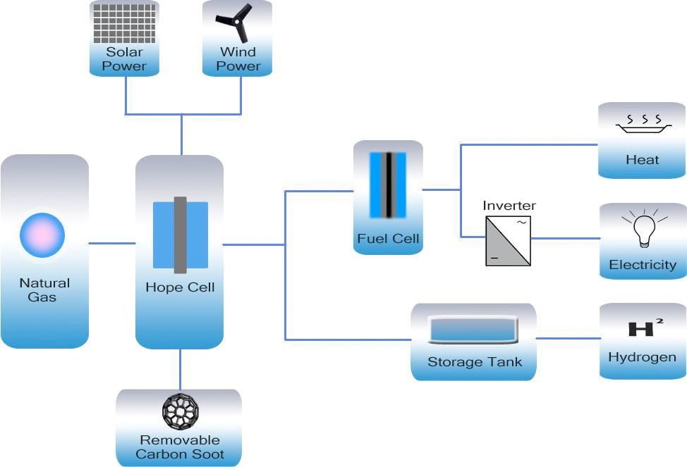
Electrical Power for the city will be provided from two sources each of which is clean [non-combustion] energy. The first source will be from wind turbines and solar panel arrays [all mounted on the ring tower roofs] with sufficient capacity to provide up to 30% of city demand [at suitable wind and light conditions] and an average year round contribution of 20%. The second source of electric power will be from a combination of cold and hot fusion direct electrical conversion processes and this plant will be housed in below ground facilities adjacent to the inner perimeter of the inner circle tower. This arrangement will thus avoid any power distribution grids above ground.

Water Supply [potable/drinking water] will be supplied from water treatment facilities located at adjacent lakeshore or sea coast. A suitably sized treated water duct will deliver the water to the Ring City complex [desalination plant at the coast, will be required if only sea water is available].

As water is such an essential and limited commodity it will be necessary, to distribute around the inner perimeter of the ring city, small treatment stations that re-process used water [plus all land sewers and building drains] for use other than potable water. The economy of water together with high density of residences will result in consumption per person being a minute fraction of that in existing city sprawl.

Sewage from the city complex will be delivered [underground] to the perimeter of the inner circle tower where pumping stations will deliver it to the sewage treatment plant located adjacent to lakeshore or sea coast.

The man-made lakes in central park are arranged such that the inner lakes are about 200 ft higher than city ground level and the outer [lower] lakes are about 20 ft. higher than city ground level such that water may cascade down to the lower lakes via ,water-falls. rapids and streams and then water returned via pumping stations [with make-up water as necessary] to the upper lakes.

A POSITIVE PROGRESSION OF A SOCIAL COMMUNITY [avoiding the charge of being a utopia]

This ring city of Babylon represents an experiment in a democratic modern and environmentally friendly community that explores urgent and necessary adjustments in lifestyle, fitness, quality of health and quality of life, by integrating all elements of the community into a tolerant and inclusive society where all businesses and individuals pay appropriate taxes with the introduction of a simple tax code where tax avoidance is difficult and easily detected and where fraud will be severely punished with heavy financial penalties and ejection of that individual or business, from the community.

The gap between minimum wage and maximum allowed income [as salary] will be reduced to a ratio of 50 to 1. Any corporate executive or other employee cannot receive any other benefit from business other than salary which specifically excludes company shares, bonuses or pensions. Income as dividends from held shares, or interest from savings accounts or bonds and money from inheritance are of course allowed but will be taxed at a higher rate [if gross income exceeds 50 to 1 ratio].

The following is the proposed tax code :-

Personal income tax :-
The first $20,000 [as annual minimum wage @2,000 hrs.] is tax exempt
Annual income above $20,000 and up to $1,000,000 is taxed @ 33%
Annual income exceeding $1,000,000 will be taxed @ 50%
Business Taxation :-
The gross annual income of businesses operating within the city limits, from sales and/or services to be taxed @ 15%
Rental [as annual lease payment to City for land and premises] to be 10% of gross income from sales and/or services.

Healthcare :-

In this modern city there will be a universal healthcare system funded [through taxation] and operated by city government. The following features will be prominent in this experimental system :-
-No for-profit entity will function in or be a component of this healthcare system.
-The prescription of drugs will not be the usual first response following the diagnosis .
-Where possible medically qualified personal should provide needed patient care in their home.
-If patient is seriously ill or incapacitated then patient should receive a doctor visit and diagnosis in their home and subsequently, if necessary, receive services of homecare [where possible] in preference to a stay in hospital.

The concentration of residences within a circle structure with continuous free subway transit serving the entire resident population, makes doctor visits and subsequent home care [as necessary] an obvious option.

Conclusion -There are no doubt, many other aspects of life in an integrated and modern community that represent a progression in the quality and stability in that society, however the preceding is a first attempt to address the enormous [but potentially rewarding] challenge.

Images

All Babylon_images [.pdf] (4M)

Ring City Plan
Babylon_images-2.jpg

Ring City Plan of Central Park
Babylon_images-3.jpg

Ring City Sectional Elevation
Babylon_images-4.jpg

Ring Tower Residences
Babylon_images-5.jpg

Ring Tower Residences – Four Bedroom
Babylon_images-6.jpg

Student Residence
Babylon_images-7.jpg

10-Stage Flash Desalinization
Babylon_images-8.jpg

This concept by J.Varney – dated July 5th. 2013


Related

Babylon and the New Enery Era [.pdf]

John Varney Home

Synopsis of recent Finnish patent application

THERMAL-ENERGY PRODUCING SYSTEM AND METHOD

Patent to be issued to Etiam Oy. Inventor: Pekka Soininen

The invention proposes to produce thermal energy in a reaction chamber from “nanoscale particle accelerators” and a nano-powder catalyst material used for promoting the formation and storage of condensed Rydberg matter.

The particle accelerators are composed of a metal material (usually powdered Ni) capable of conducting electricity, absorbing hydrogen atoms in the interstitial spaces in the metal lattice forming a metal hydride, and a dielectric material (electric field creator usually in powdered form) capable of being polarized. The nanoparticles accelerators create, enhance and focus localized electric fields and thus accelerate hydrogen ions and electrons.

The catalytic nano-powders allow for the formation and storage of Rydberg matter and inverted Rydberg matter in the same reaction chamber where the nanoscale particle accelerators are producing high-energy electrons and protons. Quantum tunneling allows high-energy protons to overcome the Coulomb barrier, which then allows nuclear fusion to take place between the protons and lattice atoms. The Rydberg matter and inverted Rydberg matter formed by local low-level electric fields condense to form condensed Rydberg matter, which when exploded by high intensity electric fields provide additional protons that increase the probability that fusion with lattice atoms takes place with the release of additional energy.

It appears that the invention itself depends on the efficacy of the reactions posited above. There appear to be two kinds of processes at work. Each process appears to produce protons, which then produce excess heat by tunneling through the Coulomb barrier, each helping the other to make the tunneling process more efficient in producing heat energy. If the inventor has a working model and that model produces energy consistent with the nuclear reactions indicated in the patent, there may actually be some credence to the claims made. This approach to explaining LENR theory is new to me and may IMO have some merit.

The inventor explains in some detail realizations of the specific materials used in the reaction chamber. These materials may be similar to those used by Rossi and Defkalion.

http://worldwide.espacenet.com/publicationDetails/description?CC=WO&NR=2013076378A2&KC=A2&FT=D&ND=3&date=20130530&DB=EPODOC&locale=en_EP

John O’ Mara Bockris: 1923-2013

Photo: John O’M. Bockris from the 2013 History of Cold Fusion Calendar month of April courtesy Infinite Energy.

Infinite Energy Magazine reports that John O’M. Bockris has crossed over on July 7. Words of remembrance are gathered in IE’s Bockris Memorial. [.pdf]

IE32He was one of the first few scientists to detect tritium from cold fusion electrolytic cells while reproducing the Fleischmann-Pons Effect (FPE) of excess heat, and he paid a price for it. Accused of fraud, and then “misconduct”, Texas A&M University’s Committee of Inquiry eventually cleared of all charges after a third and final investigation turned up no wrongdoing.

Still, an early workshop on transmutations, documented in The History of the Discovery of Transmutation at Texas A&M University [.pdf] written by Bockris, was organized in an atmosphere so hostile, the second workshop was held off-campus at a Holiday Inn, with off-duty police hired for security.

Eugene Mallove wrote a full report in Infinite Energy issue #32The Triumph of Alchemy: Professor John Bockris and the Transmutation Crisis at Texas A&M“. [.pdf]

However, Bockris told his own story in the documentary film Cold Fusion: Fire from Water written by Eugene Mallove and Jed Rothwell and directed by Chris Toussaint.

Released in 1999, Bockris speaks nonchalantly as a man at-ease who was nonplussed at the events.

“I think the main part was that, I had done work which was against the paradigm, and that’s what they were really upset about,” said Bockris.

“You know people said they’d been to our university, and some people had laughed at it, saying ‘What the heck are you doing trying to disprove the laws of nuclear physics?‘, and of course, that’s exactly what we were doing,” he laughs, ” – and succeeding.”

Watch the clip of John Bockris here. (The still image is that of George H. Miley, but Bockris begins the piece.)

One of the world’s top electrochemists, Bockris was first to use the phrase “Hydrogen Economy” in the year 1970. A prolific writer, he authored more than twenty books on electrochemistry, energy resources, and the topology of cultural paradigms. Aware of Peak Oil and the work of Richard Heinberg, he was realistic in his analyses of renewable energies, though still clear on the need for alternatives to carbon-emitting fuels. Read his Global Warming [.pdf] for a comprehensive outline of the problem.

First and foremost, Bockris was a teacher. After the passing of Martin Fleischmann, and the journal Nature‘s horrendous obituary, Bockris was one of many who wrote to protest the “gross distortion” of statements made by author Philip Ball. Bockris had supervised part of Martin Fleischmann‘s PhD thesis, calling him “a brilliant scientist”.

As a generation of new-energy researchers leaves our world behind for bigger, better beyonds, their teaching remains alive, with us here today, through the legacy of their work. You can honor the contributions of these scientists by buying their books, and giving them to schools, science clubs, and your local library.

Peace, and

Cold Fusion Now!

NAVY LENR Patent Granted – Transmutes Radioactive Waste

This U.S. Navy patent transmutes radioactive elements into less harmful elements through a benign “cold fusion” low energy nuclear reaction process. The patent was granted April 16, 2013 for a device and method that shortens the half-life of radioactive materials by increasing their rate of emissions. The process creates high pressure steam for the turbines eliminating the need for refueling of existing nuclear reactor cores.

I took a look at the U.S. Navy SPAWAR technology transfer site.

The search I made on July 9th, 2013, yielded this posted July 3rd, 2013 by the U.S Navy SPAWAR Technology Transfer folks.

The U.S. Navy LENR patent is listed under Physical Chemistry. Oddly enough, it is not listed under Radiation and Nuclear Chemistry.

This technology is now available for licensing purchase here.

Physical Chemistry

8419919: “System and Method for Generating Particles”

SPAWAR Systems Center Pacific – Technology Transfer

  • SSC Pacific currently has over 600 pieces of intellectual property (patents, patent applications, and Navy invention disclosures). Many of these properties are available for licensing through Patent License Agreements (PLAs).

  • PLAs allow companies to commercially exploit SSC Pacific-developed technology. Royalty rights, legal rights, and other terms and conditions on the use of the technology are negotiated by the company and SSC Pacific. The licensee gains the technical knowledge and financial benefits of the Government intellectual property. SSC Pacific retains the rights to use the technology for Government purposes. 

  • Licensees must complete and submit an Application for License to Practice Invention (pdf) and a commercialization plan (in essence, a business plan). These two items are a statutory requirement to license SSC Pacific technologies. If submitting the application and commercialization plan together, many of the answers on the application can refer back to the commercialization plan.

  • PLAs can be partially exclusive or nonexclusive. The partially exclusive license agreement is, in essence, an exclusive license agreement with the exception of the Government having rights. See the SSC Pacific Partially Exclusive PLA Template (pdf) for more information on what a partially exclusive PLA entails. Licensees may work with employees of SSC Pacific to further develop or test the technology through a Cooperative Research and Development Agreement (CRADA). (link)

  • Visit our technologies page (link)  to browse/search SSC Pacific technologies available for licensing or contact us (here) for more information.

In light of the continuing radioactive disasters at Fukushima and at the Hanford Nuclear Reservation facility. In light of the danger of nuclear reactors and the on site storage of spent fuel rods. In order to bring an end to nuclear fuel use. This Navy LENR technology, research and applied engineering, should be fast tracked and brought into the international field for further development. Licensing agreements for use of this technology to be distributed widely. Environmental remediation and avoidance of nuclear catastrophes is our foremost priority.

Studying the patent, I can not help but observe that this is an advanced LENR concept. The Navy has been working on this for quite some time. The patent was filed in 2007. We get to view it six years later. Now that this publicly funded research work is finally seen, it should be brought into the spotlight of the world stage immediately.

International and National lobby groups will be formed to do so.

Demand It from the Navy

COLD FUSION NOW! 

System and Method for Generating Particles – US8419919 B1

United States Navy Patent

Cold Fusion LENR Energy

Publication number – US8419919 B1

  • Publication type – Grant

  • Application number – 11/859,499

  • Publication date – Apr 16, 2013

  • Filing date – Sep 21, 2007

Inventors

Original Assignee

  • The United States Of America As Represented By The Secretary Of The Navy

  • And Jwk International Corporation – see (wikicorp) or (company link)

DETAILED DESCRIPTION OF SOME EMBODIMENTS

  • Particles are generated from the application of method. As used herein, the term “generated” is used to refer to the forming of particles through a process involving chemical and, depending upon the substrate, magnetic interaction.

  • Examples of the types of particles generated and detected may include, but are not limited to: alpha particles, beta particles, gamma rays, energetic protons, deuterons, tritons, and neutrons. The particles generated by the implementations of method may have various applications.

  • For example, the generated particles may be captured by other nuclei to create new elements, may be used to remediate nuclear waste, may be used to create strategic materials, or may be used to treat cancerous tumors.

  • As an example there are some sites that have groundwater that is contaminated with radionuclides, such as technetium, Tc-99. The particles emitted by electrochemical cell may be absorbed by the radionuclide, Tc-99 via neutron capture, transmuting it to Tc-100 with a half life of 15.8 seconds to Ru-100, which is stable where the reaction is shown by 99Tc43(n,γ)100Tc43 and the 100Tc43 β− decays to 100Ru44 with a half-life of 15.8 seconds.

RELATED POSTS

E- Cat World article April 23, 2013

USPTO Grants Patent for System for ‘Generating Particles’

Follow Navy LENR part II

“Transmutes Radioactive Wastes Now U.S. Navy and LENR Energy”

Includes U.S. Navy LENR technology patent filed in Europe

A LENR Hybrid Fusion Fission Reactor

The Global Energy Corporation GeNie Reactor

Advantages of the embodiment of the invention:

  • [014] It may be an advantage of one or more of the embodiments of the invention to provide a safer nuclear reactor.

  • [015] Another advantage of one or more of the embodiments may be to provide a nuclear reactor with an internal source of fast neutrons.

  • [016] Another advantage of one or more of the embodiments may be to provide a nuclear reactor that operates with fertile or fissile fuel.

  • [017] A further advantage of one or more of the embodiments may be to provide a nuclear reactor that consumes its own nuclear waste products.

  • [018] A further advantage of one or more of the embodiments may be to provide a means to fission spent fuel rods.

  • [019] Yet another advantage of one or more of the embodiments may be to co-generate heat while consuming nuclear fission products and unspent nuclear fuel.

  • [020] Still yet another advantage of one or more of the embodiments may be to co-generate power from a conventional steam/water cycle

  • [021] Other objects and advantages of the present invention will become apparent from the following descriptions, taken in connection with the accompanying drawings, wherein, by way of illustration and example, an embodiment of the present invention is disclosed.

Follow Navy LENR part III

“Energy Shortage – LENR Cold Fusion – Navy Guam”

  • Presented MONDAY, 13  FEB  2012

  • THE Consolidated Commission on Utilities and the Guam Power Authority are investigating a new type of “generation five” nuclear power generator – one that could potentially reduce power costs for Guam ratepayers by half or more.

  • The Variety has learned Dr. Jay W. Khim, CEO of Global Energy Corp. (GEC) based in Annandale, Va., made a presentation to the utilities commission, GPA officials and Navy engineers last month and will make another tomorrow afternoon.

  • CCU member Eloy Hara, who says he is “spearheading” the project on behalf of GEC, told Variety: “After the presentation that Dr. Khim gave to the CCU and the Guam power management team, and almost an hour-long discussion afterward … we were all awed by the technology.

Follow Navy LENR part IV

“Mineta, Davis, Carlucci Global Energy Corporation LENR Navy Guam”

“You have to change the basic science of nuclear power,” Khim explained. “We’ve been working with the U.S. Navy for about 22 years and the basic science phase is now over.

Now we’re going into commercial development, which the Navy is not going to do.” But Khim says the science has been repeatedly duplicated by the Navy, and has been proven, recognized and published.

Officials of the Navy on Guam, including Capt. John V. Heckmann Jr., CO of Naval Facilities and a professional engineer, attended the GEC briefing.

The GEC board of directors, Khim says, includes some well-known Washington D.C. Players, including former Secretary of Defense Frank Carlucci, former Congressman and Secretary of Transportation Norman Mineta, and former U.S. Congressman Tom Davis, among others.

IN LIGHT OF THIS The Cold Fusion Now

LOVE IN SCIENCE AWARD

Goes to

Edward Esko

Quantum Rabbit

Infinite Energy Magazine

And the New Energy Foundation

LENR-Induced Transmutation of Nuclear Waste

INFINITE ENERGY • ISSUE 104 • JULY/AUGUST 2012


Edward Esko

  • Abstract —

  • Quantum Rabbit (QR) research on the low-energy fusion and fission (low-energy nuclear reactions, or LENR) of various elements indicates possible pathways for applying that process to reducing nuclear materials.

  • In a New Energy Foundation (NEF)-funded test conducted at Quantum Rabbit lab in Owls Head, Maine, QR researchers initiated a possible low-energy fission reaction in which 204Pb fissioned into 7 Li and 197Au (204Pb → 7 Li + 197Au).1

  • This reaction may have been triggered by a low-energy fusion reaction in which 7 Li fused with 32S to form 39K (7 Li + 32S →19K).

  • These results confirmed earlier findings showing apparent low-energy fusion and fission reactions.2 Moreover, subsequent research with boron indicates apparent low-energy fusion reactions in which boron fuses with oxygen to form aluminum and with sulfur to form scandium.3

  • At the same time, the QR group has achieved what appear to be low-energy transmutations of carbon using carbon-arc under vacuum and in open air.4

  • The research group at QR believes these processes can be adapted to accelerate the natural decay cycle of uranium-235, plutonium-239, radium-226 and the fission products cesium-137, iodine-129, technetium-99 and strontium-90 with the long-term potential of reducing the threat posed by radioactive isotopes to human health and the environment.

NAVY LENR Summary

DETAILED DESCRIPTION OF SOME EMBODIMENTS

  • FIG. 1 shows a flow chart of an implementation of a method for generating particles 10. One implementation of method 10 may utilize an electrochemical cell 100 as shown in FIGS. 4 and 5. As such, method 10 will be discussed with reference to electrochemical cell 100. Method 10 may be performed at conditions of ambient temperature and standard atmospheric pressure. Method 10 may begin at step 20, where a current may be supplied to the electrodes of an electrochemical cell according to a first charging profile. For example, step 20 may involve supplying current to the positive electrode, anode 130, and the negative electrode, cathode 132, of electrochemical cell 100. Current may be supplied to anode 130 and cathode 132 by connecting a galvanostat/potentiostat 140 to anode 130 and cathode 132. Step 20 is discussed in further detail with regard to FIG. 2. Following step 20, method 10 may proceed to step 30. Step 30 may involve maintaining a generally constant current between the positive and negative electrodes during the first charging profile such that deposition of metal 172 on the cathode occurs in the presence of evolving deuterium gas during electrolysis of an electrolytic solution. As an example, step 30 may involve maintaining a generally constant current between the anode 130 and cathode 132 during the first charging profile. Maintaining a generally constant current serves to ensure that deposition of metal 172 that substantially absorbs deuterium on cathode 132 occurs in the presence of evolving deuterium gas 174 during electrolysis of electrolytic solution 170 (see FIG. 5). A generally constant current may be defined as current that is stable, but that may have minor fluctuations. Step 30 may be performed by connecting a galvanostat/potentiostat 140 to anode 130 and cathode 132.
  • Method 10 may next proceed to step 40, where electrochemical cell 100 may be exposed to an external field, such as a magnetic field. For example, step 40 may be performed by positioning magnets 160 and 162 opposite one another on opposing sides of electrochemical cell 100 (see FIGS. 4 and 5). Step 40 may occur during the deposition of the metal on the cathode. In other embodiments, step 40 may occur after the termination of the deposition of the metal on the cathode. The determination that the deposition of the metal on the cathode has terminated may be made by a visual inspection that the plating solution within electrolytic solution 170 has turned from a red-brown color to clear. The plating solution turns clear when metal has all been plated onto cathode 132. Method 10 may then proceed to step 50, where a current may be supplied to the electrodes according to a second charging profile during the exposure of the electrochemical cell to the external field. For example, step 50 may involve using a power source to supply a current to anode 130 and cathode 132 according to a second charging profile during the exposure of electrochemical cell 100 to an external magnetic field (not shown).
  • Particles are generated from the application of method 10. As used herein, the term “generated” is used to refer to the forming of particles through a process involving chemical and, depending upon the substrate, magnetic interaction. Examples of the types of particles generated and detected may include, but are not limited to: alpha particles, beta particles, gamma rays, energetic protons, deuterons, tritons, and neutrons. The particles generated by the implementations of method 10 may have various applications.
  • Government DOE control of LENR since 1989. 

  • Technology quietly announced July 3rd, 2013.

  • When few would be watching.

  • Years before 2007… They knew of LENR nuclear remediation. 

  • We were not allowed to have this knowledge

  • They did not share it. They hid it.

  • A Low key Manhattan Project – Few research papers.

  • U.S. Patent sequestered for almost six years.

  • No SPAWAR ICCF presentation of nuclear waste remediation.

  • No SPAWAR presentation of LENR nuclear waste remediation at THE ASME – ICEM2013 15th INTERNATIONAL CONFERENCE ON ENVIRONMENTAL REMEDIATION AND RADIOACTIVE WASTE MANAGEMENT. 

  • U.S. LENR reactor patent was quietly filed in Europe 2008. 

  • Company attempted to quietly launch  in Guam 2012.

  • GEC pitched it as a fast breeder reactor. No mention of LENR Technology or Breakthrough Cold Fusion Science.

  • Even more evidence of covert acts and collusion.

  • Technology listed as physical chemistry, not as a nuclear technology.

  • 2112 GeNie presentation in Guam.  

  • 2012 SPAWAR ICCF presentation.

  • Compare the two. No mention of GeNie at ICCF 2012.

  • GeNie LOW COST Guam Powerplant. 50MW – $250 million

  • Guam reactor to be fueled with fresh uranium.

  • Not transmuting nuclear waste.

  • Not ending nuclear reactor refueling.

  • No presentation planned for 2013 ICCF.

  • COLD FUSION NOW !!

  • Remediation of nuclear waste NOW!!

  • End refueling of nuclear reactors NOW!!

  • Lower our risk factor for nuclear catastrophes NOW!!

  • This technology was hidden!

  • Absolutely without a doubt!

  • For example, the generated particles may be captured by other nuclei to create new elements, may be used to remediate nuclear waste, may be used to create strategic materials, or may be used to treat cancerous tumors.

  • As an example there are some sites that have groundwater that is contaminated with radionuclides, such as technetium, Tc-99.

  • The particles emitted by electrochemical cell 100 may be absorbed by the radionuclide, Tc-99 via neutron capture, transmuting it to Tc-100 with a half life of 15.8 seconds to Ru-100, which is stable where the reaction is shown by .sup.99Tc.sub.43(n,.gamma.).sup.100Tc.sub.43 and the .sup.100Tc.sub.43 .beta..sup.- decays to .sup.100Ru.sub.44 with a half-life of 15.8 seconds.

  • FIG. 2 shows a flow chart of an implementation of step 20 of method 10. Step 20 may include more than one current level and more than one time period, wherein each of the current levels is supplied across the anode and the cathode for one of the time periods. Step 20 may be performed to assure good adherence of the palladium, a deuterium absorbing metal, to cathode 132, which may be a wire having a length of 2 cm and a diameter of 0.5 cm. Step 20 may involve low current densities for adhering the palladium to cathode 132. As an example, step 20 may begin at step 22, where a reducing current of 100 .mu.A may be supplied to the anode and cathode for a time period of about twenty-four hours. Next, step 24 may involve supplying a reducing current of 200 .mu.A to anode 130 and cathode 132 for a time period of about forty-eight hours. Step 20 may then proceed to step 26, where a reducing current of 500 .mu.A may be supplied to anode 130 and cathode 132 until the completion of the deposition process. The completion of the deposition process will occur when the plating solution appears clear as described above. As an example, the amount of time required for the completion of the deposition process may be between approximately 3 and 7 days, depending upon the surface area of cathode 132 and the first charging profile used.
  • As current is applied, Pd is deposited on the cathode. Electrochemical reactions occurring at the cathode include: Pd.sup.2++2e.sup.-Pd.sup.0 D.sub.2O+e.sup.-D.sup.0.+-.OD.sup.- (Eq. 1) Once formed, the D.sup.0 is either absorbed by the Pd or binds to another D.sup.0 to form a deuterium molecule, D.sub.2. At standard temperature and pressure, D.sub.2 is a gas. The result is that metallic Pd is deposited on the cathode in the presence of evolving D.sub.2.
  • FIG. 3 illustrates a flow chart of an implementation of step 50 of method 10. Step 50 may be performed to load metal 172 on cathode 132 with deuterium. In one embodiment, step 50 may involve more than one current levels and more than one time periods, wherein each of the current levels is supplied across the anode and the cathode for one of the time periods. In one embodiment, step 50 may involve levels of increasing current density to load the palladium lattice with deuterium such that the ratio of deuterium to palladium is .gtoreq.1. As an example, one implementation of step 50 may begin at step 52, where a current of 1 mA is supplied to anode 130 and cathode 132 for a time period of about two hours. Next, step 54 may involve supplying a current of 2 mA to anode 130 and cathode 132 for a time period of about six hours. Next, step 56 may involve supplying a current of 5 mA to anode 130 and cathode 132 for a time period of about twenty-four hours. Next, step 58 may involve supplying a current of 10 mA to anode 130 and cathode 132 for a time period of about twenty-four hours. Next, step 60 may involve supplying a current of 25 mA to anode 130 and cathode 132 for a time period of about twenty-four hours. Next, step 62 may involve supplying a current of 50 mA to anode 130 and cathode 132 for a time period of about twenty-four hours. Next, step 64 may involve supplying a current of 75 mA to anode 130 and cathode 132 for a time period of about twenty-four hours. Finally, step 66 may involve supplying a current of 100 mA to anode 130 and cathode 132 for a time period of about twenty-four hours.
  • Referring to FIGS. 4 and 5, electrochemical cell 100 may include an electrolytic solution 170, an anode 130, and a cathode 132. Electrolytic solution 170 may comprise a metallic salt having a first metal that substantially absorbs deuterium when reduced to an atomic state, and a supporting electrolyte, each dissolved in heavy water. As an example, the metallic salt may be selected from the group of transition metals, such as palladium. In one embodiment, where the deuterium atoms bind to one another to create deuterium gas, the reduced metal 172, such as palladium, absorbs deuterium 174. In another embodiment, as shown in FIG. 5, gaseous deuterium atoms collect on the surface of cathode 132 and enter into the lattice of metal 172 when in a reduced state. In one implementation, electrolytic solution 170 comprises 20-25 mL solution of 0.03 M palladium chloride and 0.3 M lithium chloride in deuterated water.
  • Cathode 132 may be partially immersed in electrolytic solution 170. Cathode 132 may comprise a second metal that does not substantially absorb deuterium 174 and is generally stable in electrolytic solution 170 when cathode 132 is polarized. For example, cathode 132 may be comprised of Au, Ag, Pt, as well as their alloys. In some embodiments, cathode 132 may comprise a second metal that does absorb deuterium 174 and is generally stable in electrolytic solution 170 when cathode 132 is polarized. As an example, cathode 132 may be comprised of Ni or its alloys. Cathode 132 may be formed into various shapes, such as a wire, rod, screen, or foil. In some embodiments, cathode 132 may be shaped as a wire having a diameter of 0.25 mm and a length of 2.5 cm. Anode 130 may also be partially immersed in electrolytic solution 170 and may be stable in electrolytic solution 170 when anode 130 is polarized. Anode 130 may be manufactured from any electrically conductive material which is stable in electrolytic solution 170, such as Pt, as well as their alloys. The term “stable” with reference to anode 130 and cathode 132 means that the materials employed in the construction of anode 130 and cathode 132 do not substantially corrode when they are polarized and generally do not react with the electrolyte or products of electrolysis. Anode 130 may be formed into various shapes, such as a wire, rod, screen, or foil. As an example, anode 130 may be shaped as a wire having a diameter of 0.25 mm and a length of 30 cm.
  • FIG. 4 illustrates a front perspective view of an embodiment of a system 100 for generating particles using an external magnetic field. System 100 may include an electrochemical cell 110, power supply 140, and magnets 160. Cell 110 may include a body portion 120 and a top portion 122. Cell 110 may be rectangular, square, cylindrical, cubical, or various other shapes as recognized in the art. Cell 110, an example of which is commercially available from Ridout Plastics, model AMAC, part number 752, may be comprised of various non-metallic materials that do not react with the electrolyte, such as butyrate. Body portion 120 may be configured to contain an electrolytic solution 170 (see FIG. 5). As an example, body portion 120 may be cubic in shape and may be comprised of a non-conductive material, such as plastic. Top portion 122 may be configured to cover body portion 120. Top portion 120 may be comprised of a non-conductive material, such as plastic. Top portion 122 may contain an opening 124 therein where an anode 130 may be passed therethrough, and also an opening 126 where a cathode 132 may be passed therethrough. Top portion 122 may also contain an opening 128 for venting purposes.
  • Anode 130 may comprise a wire mounted on a support 150 and may be partially immersed in electrolytic solution 170 (see FIG. 5). Support 150 may be comprised of a chemically inert material, such as polyethylene. Cathode 132 may be shaped as a single wire (as shown in FIG. 7A), a screen (as shown in FIG. 7B), or a foil (as shown in FIG. 7C). One end 131 of anode 130 may be connected to power supply 140. One end 133 of cathode 132 may be connected to power supply 140. Power supply 140 may be a potentiostat/galvanostat, an example of which is commercially available from Princeton Applied Research, model 363. The other end 135 of anode 130 may be coupled to a support 150 (see FIG. 5), which may be secured to body portion 120. Cathode 132 may be coupled to a particle detector 152 that may be attached to body portion 120. Both particle detector 152 and cathode 132 may be mounted to body portion 120. In one embodiment, particle detector 152 may be contiguous with cathode 132. In another embodiment, detector 152 may be in proximity to cathode 132, such that particles emitted from cathode 132 may contact particle detector 152. For example, particle detector 152 may be positioned adjacent to cathode 132. As another example, particle detector 152 may be positioned between cathode 132 and body portion 120. Particle detector 152 may be used to detect the occurrence of particles.
  • Particle detector 152 may be comprised of a non-metallic material. In one implementation, particle detector 152 may be comprised of CR-39 material. CR-39 is a thermoset resin that is chemically resistant to the electrolyte and to electromagnetic noise. CR-39 may be commercially obtained from Landauer. Particle detector 152 may comprise various shapes. As an example, particle detector 152 may be rectangular in shape with dimensions of 1 cm.times.2 cm.times.1 mm. When traversing a plastic material such as CR-39, particles create along their ionization track a region that is more sensitive to chemical etching than the rest of the material. After treatment with an etching agent, tracks remain as holes or pits that may be seen with the aid of an optical microscope. The size, depth of penetration, and shape of the tracks provides information about the mass, charge, energy, and direction of motion of particles generated by method 10. Neutral particles, like neutrons, will produce knock-ons, or charged particles resulting from the collision with the neutron that will leave ionization tracks, or, with sufficient energy (e.g. >12 MeV) cause .sup.12C present in the CR-39 resin to fission into 3 charged .alpha. particles that will leave ionization tracks.
  • Magnets 160 and 162 may be positioned adjacent to body portion 120 such that a magnetic field is created within electrochemical cell 100 between anode 130 and cathode 132 and though electrolytic solution 170. In some embodiments, the magnetic field created between magnets 160 and 162 may be sufficient to hold magnets 160 and 162 in position adjacent to body portion 120. In other embodiments, magnets 160 and 162 may be attached to body portion 120. Magnet 160 may be positioned adjacent to the surface of body portion 120 that contacts support 150. Magnet 162 may be positioned adjacent to the surface of body portion 120 that contacts detector 152. Magnets 160 and 162 may be comprised of various magnetic materials, such as NeFeB. As an example, the dimensions of magnets 160 and 162 may be 1 in.times.1 in.times.0.25 in. Magnets 160 and 162 may be commercially obtained from Dura Magnetics, part number NS-10010025. As an example, the external magnetic field created by magnets 160 and 162 may have a magnetic flux between about 1800 and 2200 Gauss. Magnets 160 and 162 may be permanent magnets or may be electromagnets.
  • FIG. 5 illustrates a cross-section view of a cell 110 during a co-deposition process. As shown, cell 110 is connected to power supply 140 and includes electrolytic solution 170 therein. Electrolytic solution 170 may comprise a soluble metallic salt (not shown) having a first metal, such as palladium, and a supporting electrolyte (not shown), wherein the palladium and chlorine are combined to form a palladium chloride complex anion, PdCl.sub.4.sup.-. The palladium chloride complex anion may be dissolved in heavy water (D.sub.2O) (not shown), with the palladium absorbing deuterium 174 when in a reduced state. The supporting electrolyte may include an ionizable salt to increase solution conductivity. Examples of ionizable salts may include: alkali metal chlorides, nitrates, and perchlorates. In one embodiment, electrolytic solution 170 may be comprised of a metallic salt such as 0.05 M PdCl.sub.2 and a salt such as 0.3 M LiCl dissolved in 99.9 percent pure heavy water. During the co-deposition process, metal 172 infused with deuterium 174 may be deposited on cathode 132, while oxygen 176 accumulates around anode 130.
  • FIG. 6 illustrates a cross-section view of an embodiment of a system 200 for generating particles using an external electric field. System 200 may include an electrochemical cell 210, power supply 240, and external electrodes 260 and 262. Cell 210 may include a body portion 220 and a top portion 222. Top portion may contain an opening 224 (not shown) therein where an anode 230 may be passed there through, and also an opening 226 (not shown) where a cathode 232 may be passed there through. Top portion 222 may also contain an opening 228 (not shown) for venting purposes. Cell 210 may be rectangular, square, cylindrical, or various other shapes as recognized in the art. Cell 210 may be comprised of various non-metallic materials, such as butyrate. Anode 230 and cathode 232 may be connected to power supply 240. Power supply 240 may be a potentiostat or a galvanostat. Anode 230 is attached to a support 250. Cathode 232 may be coupled to a particle detector 254 that is attached to a support 256. Particle detector 254 may be comprised of a non-conductive material. In one implementation, particle detector 254 is comprised of CR-39 material.
  • Electrodes 260 and 262 may be positioned adjacent to body portion 220 such that an electric field may be created between anode 230 and cathode 232. In some embodiments, electrodes 260 and 262 may be secured to body portion 220 by an adhesive. Electrodes 260 and 262 are positioned adjacent to the surface of body portion 220 perpendicular to anode 230 and cathode 232. Electrodes 260 and 262 may be comprised of various conductive materials as recognized by one with ordinary skill in the art, such as copper. As an example, electrodes 260 and 262 may be less than one inch in diameter. Electrode 260 may be connected to a regulated high voltage source 264 via wire 266, whereas electrode 262 may be connected to regulated high voltage source 264 via wire 268. Wires 266 and 268 may comprise any suitable electrical wire as recognized by one with ordinary skill in the art. An example of a voltage source 264 that may be utilized with system 200 is voltage source model 4330, which may be commercially obtained from EMCO. Voltage source 264 may be used to apply 6000V DC (with about 6% AC component) across electrodes 260 and 262.
  • Electrochemical cell 210 includes an electrolytic solution 270. Electrolytic solution 270 may comprise a metallic salt having a first metal that substantially absorbs deuterium when in a reduced state (not shown), and a supporting electrolyte (not shown), each dissolved in heavy water (not shown). As an example, the metallic salt may be selected from the group of transition metals, such as palladium. In one embodiment, where the deuterium atoms bind to one another to create deuterium gas, the reduced deuterium absorbing metal 272, such as palladium, absorbs deuterium 274. In another embodiment, deuterium atoms collect on the surface of cathode 232 and enter into the lattice of deuterium absorbing metal 272 when in a reduced state. In one implementation, electrolytic solution 270 comprises 20-25 mL solution of 0.03 M palladium chloride and 0.3 M lithium chloride in deuterated water.
  • Referring to FIGS. 7A-7C, FIG. 7A shows a front view of one side of an embodiment of system 100, illustrating an embodiment of the cathode 132. As shown, cathode 132 is attached to detector 152. In this implementation, cathode 132 consists of a wire 134. As an example of a commercially available wire 134, may be obtained from Aldrich, Au wire part number 326534 or Pt wire part number 349402. The cathode may be 0.25 mm in diameter, and be 3 cm in length. FIG. 7B illustrates a front view of one side of an embodiment of system 100, illustrating another embodiment of cathode 132. As shown, cathode 132 is attached to detector 152. In this implementation, cathode 132 is formed as a screen 138. Screen 138 may serve to increase the surface area for particle emission. Screen 138 may be comprised of various metallic materials, such as Ni, Cu, Ag, and Au. As an example, a screen 138 commercially available from Delker, part number 3 Ni 5-077, is comprised of nickel, is 3 cm in size, has a thickness of 0.08 mm, and has eyelet dimensions of 1.5 mm.times.2.0 mm. FIG. 7C illustrates a front view of one side of an embodiment of system 100, illustrating another embodiment of cathode 132. As shown, cathode 132 is attached to detector 152. In this implementation, cathode 132 is formed as a foil 139. Foil 139 may serve to increase the surface area for particle emission. Foil 139 may be comprised of various metallic materials, such as Ni, Cu, Ag, and Au. As an example, a foil 139 commercially available from Aldrich, part number 349267, is 2.5 cm in size and has a thickness of 0.025 mm.
  • In the absence of an external electric/magnetic field, Scanning Electron Microscope (SEM) analysis of electrodes prepared by Pd/D co-deposition exhibit highly expanded surfaces consisting of small spherical nodules to form a cauliflower-like morphology. Cyclic voltammetry and galvanostatic pulsing experiments indicate that, by using the co-deposition technique, a high degree of deuterium loading (with an atomic ratio D/Pd>1) is obtained within seconds. These experiments also indicate the existence of a D.sub.2.sup.+ species within the Pd lattice. Because an ever expanding electrode surface is created, non-steady state conditions are assured, the cell geometry is simplified because there is no longer a need for a uniform current distribution on the cathode, and long charging times to achieve high deuterium loadings are eliminated.
  • Using the Pd/D co-deposition process, radiation emission and tritium production were documented. The results indicated that the reactions were nuclear in origin and that they occurred in the subsurface. To enhance these surface effects, experiments were conducted in the presence of either an external electric or magnetic field. SEM analysis showed that when a polarized Au/Pd/D electrode was exposed to an external electric field, significant morphological changes were observed. These changes ranged from re-orientation and/or separation of weakly connected globules, through forms exhibiting molten-like features. EDX analysis of these features showed the presence of additional elements (in an electric field Al, Mg, Ca, Si, and Zn; in a magnetic field Fe, Cr, Ni, and Zn) that could not be extracted from cell components and deposited on discrete sites.
  • To verify that the new elements observed on the cathodes were nuclear in origin, the Pd/D co-deposition was done in the presence of a CR-39 detector. CR-39 is a polyallydiglycol carbonate polymer that is widely used as a solid state nuclear track dosimeter chip. When traversing a plastic material such as CR-39, charged particles create along their ionization track a region that is more sensitive to chemical etching than the rest of the bulk. After treatment with an etching agent, tracks remain as holes or pits and their size and shape can be measured.
  • It should be noted that, in the area of modern dosimetry, CR-39 dosimeter chips are the most efficient detectors for the detection of light particles (alphas or protons). Experiments were conducted in which either a Ni screen or Au/Ag/Pt wire was wrapped around a CR-39 chip and was then used as the substrate for the Pd/D co-deposition. After the Pd was completely plated out, the cell was exposed to either an external electric or magnetic field. The experiment was terminated after two days and the CR-39 chip was etched using standard protocols (6.5 N NaOH at 70.degree. C. for 6-7 hrs). After etching, the chip was examined under a microscope.
  • The Pd/D co-deposition generated pits in CR-39 have the same properties as those created by nuclear particles as shown in FIGS. 8A and 8B. FIGS. 8A and 8B are microphotographs 300 and 400, respectively, of tracks in CR-39 due to an alpha source. When the microscope optics are focused on the surface of the detector, as shown in FIG. 8A, it can be seen that the tracks 310 are symmetrical in shape and dark in color. When the microscope optics are focused inside the pits 410, as shown in FIG. 8B, bright spots 420 are observed. Tracks have a conical shape. The bright spot 420 is caused by the bottom of the track acting like a lens when the detector is backlit. The dark, symmetrical shapes with bright spots at their centers are diagnostic of nuclear generated tracks.
  • FIGS. 8C and 8D show microphotographs 500 and 600, respectively, of Pd/D co-deposition generated tracks 510 and 610 obtained by focusing the microscope optics on the surface and the bottom of the pits, respectively. It can be seen that the Pd/D co-deposition generated tracks are dark and symmetrical in shape, with bright spots 520 and 620, respectively, inside them.
  • FIGS. 9A and 9B show images taken of the CR-39 detector after a Pd/D co-deposition experiment in a magnetic field. FIG. 9A illustrates a magnified image 700 of a CR-39 taken after a Pd/D co-deposition experiment in a magnetic field in accordance with an embodiment of the system and method for generating particles. FIG. 9B illustrates a further magnified image of image 700.
  • The electrode substrate used to create these images is a 0.25 mm diameter Ag wire. Visible inspection of the CR-39 chip showed a cloudy area where the electrode substrate was in close proximity to the CR-39 detector. The cloudy area 710 shown in FIG. 9A is approximately 0.5 mm wide and 4.6 mm long. The fact that the cloudy area was only observed where the detector was in close proximity to the cathode indicates that the cathode has caused the cloudiness. The 500.times. magnification of the center of the cloudy area shown in FIG. 9B illustrates the presence of numerous overlapping tracks 720, both large and small. The number of tracks is far more than are observed in laser fusion experiments (typically DD or DT).
  • FIGS. 10A and 10B show a side-by-side comparison of features observed when the detector is exposed to depleted U and a detector that has undergone exposure to a Pd/D co-deposition experiment in the presence of an external electric field. FIG. 10A illustrates a magnified image 800 of a CR-39 detector exposed to depleted uranium. FIG. 10B illustrates a magnified image 900 of a CR-39 detector exposed to a Pd/D co-deposition experiment performed on a Au wire in the presence of a 6000V external electric field in accordance with the disclosed subject matter. Since the features look the same, and since depleted Uranium is giving off alphas, it stands to reason that the features observed for the co-deposition experiment are also due to high energy particles. These particles can be either alphas, protons, or neutrons.
  • It should be noted that in the absence of an external electric/magnetic field, when Ni screen is used as the cathode, no tracks are observed on the CR-39 chip, as shown in FIG. 11. FIG. 11 illustrates an image 1000 of a CR-39 detector indicating X-ray emission, in accordance with an embodiment of the system and method for generating particles. Instead of tracks, the impression of the electrode substrate is observed in the CR-39 detector which has been caused by the emission of soft X-rays from the cathode.
  • The size of the tracks is proportional to the energy of the particle that created the track. It has been observed that the energy of the particles created in these experiments can be controlled by the electrode substrate. When the Pd/D co-deposition reaction is done on a light Z material such as Ni, the particles are small and homogeneous in size, as shown in image 1100 shown in FIG. 12A. However, when the reaction is done on a higher Z material, such as Ag, Au, or Pt, both large and small particles are observed, as shown in FIGS. 9A, 9B, 10B, 12A, and image 1200 shown in FIG. 12B.
  • FIG. 13A shows an SEM image 1300 of the Pd deposit on Au foil that has been exposed to a magnetic field. The Lorentz lines of the magnetic field have caused the Pd micro-globules to form star-like features. FIGS. 13B-13D show images 1400, 1500, and 1600, respectively, taken of a CR-39 detector after a Pd/D co-deposition experiment in a magnetic field using a Ag wire cathode. FIG. 13B shows that the tracks coincide with the Pd deposit indicating that the Pd deposit is the source of the tracks. FIGS. 13C and 13D show magnified images of the tracks. The tracks vary in size indicating that particles of different types and energies are being produced.


Inventors: Boss; Pamela A. (San Diego, CA), Gordon; Frank E. (San Diego, CA), Szpak; Stanislaw (Poway, CA), Forsley; Lawrence Parker Galloway (San Diego, CA)
Applicant:
Name City State Country Type

Boss; Pamela A.
Gordon; Frank E.
Szpak; Stanislaw
Forsley; Lawrence Parker Galloway
San Diego
San Diego
Poway
San Diego
CA
CA
CA
CA
US
US
US
US
Assignee: JWK International Corporation (Annandale, VA)
The United States of America as represented by the Secretary of the Navy (Washington, DC)
Family ID: 48049106
Appl. No.: 11/859,499
Filed: September 21, 2007


The Navy LENR – A Four Part Series

You are viewing Navy LENR Part I

Navy LENR Part II

Navy LENR Part III

Navy LENR Part IV 

International experts on low-energy nuclear reactions meet at Mizzou

Original article by Nancy Moen on Mizzou News here.

A cool scientific mystery is drawing researchers worldwide to Mizzou for a week in July to investigate recent developments in understanding how nuclear fusion could occur at or near room temperature.

Scientists representing the U.S. and 18 countries internationally will gather July 21–27 at the International Conference on Condensed Nuclear Matter Science to share information on low-energy nuclear reactions (LENR) that could someday provide a new energy source.

The idea of usable low-energy nuclear reactions is compelling to countries worldwide. Participants of the ICCF-18 conference include distinguished nuclear physicists and related research specialists from countries such as Italy, China, Japan, India, Russia, South Korea and the United Arab Emirates.

The researchers are looking for the capability to eventually produce high-performance, inexpensive, clean energy with few or no emissions. Such a sustainable energy source could eliminate the problems of greenhouse gases and heavy air pollution.

For years, scientists have either experienced or read reports of unexplained substantial levels of excess heat thought to be caused by nuclear phenomena that deviate from what is expected.

The regularity of these anomalous heat occurrences — reported by scientific observation worldwide — continues to pique interest, and logical conclusions seem to indicate the existence of an entirely new nuclear reaction that could become a source of energy.

Global interest

hoto of Vice-Chancellor of Research Robert Duncan by Shane Epping
While in graduate school at the University of California, Santa Barbara, working toward a PhD in low-temperature physics, Robert Duncan designed liquid helium cells. The glass sphere is a sample of helium gas, which is how gasses were stored and transported long ago. Photo by Shane Epping
Leading the conference is MU Vice Chancellor for Research Rob Duncan, who oversees MU’s research and facilities. Duncan says it has taken years for mainstream scientific communities to realize this science is valid and real.

“It has been undervalued and treated as a ‘pariah science’ in the past, but now the world is beginning to realize how important it is,” he says.

An expert in measuring energy, Duncan has published extensively in low-temperature physics. Among his $8 million of funded projects, Duncan developed ultra-sensitive measuring equipment — specifically the best thermometer made in its temperature range — for a proposed NASA experiment in space aboard the 2005 International Space Station.

At the request of CBS television’s 60-Minutes in 2009, Duncan served as an independent scientist to test the validity of research in low-energy nuclear reactions by examining the objective scientific methods used in the experiments.

How LENR works

The ingredients involved in a low-energy nuclear reaction can be quite simple: deuterium, which is a type of heavy hydrogen (found in ocean water), a palladium wire and an electric current.

Researchers become very excited when far more energy comes out of the apparatus than was put in. That’s anomalous heat. These levels of anomalous heat are often more than a thousand times greater than what could be produced by a chemical process.

In recent work, researchers have made advancements in understanding the physics and in developing small units capable of initiating low-energy reactions, but the mechanisms of the phenomena still pose many questions. Improved research methodology may be the key that unlocks the mysteries of a potentially limitless supply of energy for global use.

The challenge is to determine the physical mechanisms causing excess thermal energy, the “whys” and “hows,” if you will. It’s not easy because measuring the input power is tricky, and the heat isn’t necessarily produced on demand. It can take days or even weeks for the heat to appear.

“We don’t fundamentally understand the process yet. In the past, only one in 10 or so attempts actually produced excess heat,” Duncan says. Excess heat is a comparison of the amount of heat produced to the amount of energy put in.

Experiments then and now

The first report of a possible low-energy nuclear reaction occurred in a 1926 test conducted in Germany by Austrian-born scientists Friedrich Paneth and Kurt Peters of the Berlin University Institute of Chemistry. The researchers were experimenting with palladium loaded with hydrogen. They reported that the process produced helium but later retracted their findings.

In 1989, electrochemists Martin Fleischmann and Stanley Pons at the University of Utah reported excess heat in their “cold fusion” experiments, but their work was later discredited when other researchers were unable to reproduce the results. “We understand now why these results were not immediately reproducible,” Duncan says.

Although the early experiments were difficult to replicate, other researchers through the years have observed similar anomalous heat effects in low-temperature nuclear research at several laboratories, including the Naval Research Laboratory, Los Alamos National Laboratory, ENEA (the national energy lab of Italy) and Bhabha Atomic Research Centre in Bombay, India.

In 2009, when Duncan accompanied the 60 Minutes news team on an investigation of claims of LENR at Energetics Technologies in Israel, he was a good choice because he counted himself among the skeptics.

For two days on site, Duncan asked questions, measured, checked numbers and looked for errors and other explanations. What he found was repeatable results, leading him to conclude that “excess heat is quite real.” 60 Minutes broadcast his reports on a segment airing that year.

“In Israel, I found how important the research was. I think it surprised a lot of people when a main-street physicist found the research credible. Since then, there have been exciting new developments,” Duncan says.

Researchers working independently in 20 different laboratories have repeated the results, finding excess heat in low-temperature nuclear experiments, Duncan says. Some of those have been confirmed scientifically, making the study of LENR a new and real science.
Fascinating potential

Conference attendees will go into extreme depth of this phenomenon, which is just beginning to be understood. One of the major questions being considered is whether researchers can produce excess heat on demand.

In addition to serious scientific debate, there will be discussion of opportunities in research, engineering and the development of technology.

The many participants have a lot to share. Among them, Vittorio Violante, representing ENEA, the Italian Agency for Energy and Economic Development, will lead a panel on some of the best recent work in condensed matter nuclear science.

Electrochemist Michael McKubre, director of SRI International in California, will discuss a new technique he developed to perform a range of critically important experiments. McKubre is recognized internationally for his work in examining potential new energy sources and has been at the top of his field for the past 24 years. He also was featured in the 60 Minutes report on cold fusion.

Speakers include David Kidwell of the U.S. Naval Research Laboratory; Professor Emeritus Jirohta Kasagi of Tohoku University in Japan; and Thomas Passell of TOP Consulting, a retired project manager for Electric Power Research Institute. Attendees are from top laboratories and research institutions such as the Hoover Institute, MIT and the Aerospace Corporations.

Visit the conference website for a list of conference attendees and the topics of their presentations. Members of the press are invited to register to attend.

MU’s nuclear research facilities

For the first time in 20 years, the ICCF conference is being held on a major research university campus, an achievement for MU and one that brings new opportunities, Duncan says.

Mizzou’s facilities offer a rich combination of ongoing research, and the university recently acquired a new, prestigious $3 million grant from the National Science Foundation specifically to investigate and apply neutron scattering, which has already begun.

Conference attendees will tour MU’s nuclear research facilities:

The MU Research Reactor is the nation’s largest university-operated research reactor, making possible advances in basic and applied sciences across multiple disciplines.

With seven collaborative scientific groups, the Sidney Kimmel Institute for Nuclear Renaissance is dedicated to finding the origin of anomalous heat effects using a sound materials-science approach.

The Nuclear Science and Engineering Institute is becoming a global leader in nuclear– engineering education and research with a mission to offer degrees in nuclear engineering.

The International Center for Nano/Micro Systems and Nanotechnology provides equipment supporting research in micro/nano-fabrication and nanotechnology.

The International Institute of Nano and Molecular Medicine is dedicated to the discovery and application of fundamental and translational medical science based on previously unexplored chemistry combined with nanotechnology and the biosciences.

Visit conference registration page here.

Original article by Nancy Moen on Mizzou News here.

HOPE cell offers clean fuel for Hydrogen Economy

Video: HOPE plasma cell #4 view from top

Early cold fusion researcher John O’M. Bockris is credited with coining the term “hydrogen economy” in 1970 while a Professor at University of Pennsylvania. Twenty years later, and one of the top electro-chemists in the world, Bockris became an embattled academic at Texas A&M University when he found positive results confirming the nuclear nature of the Fleischmann-Pons Effect (FPE).

His prescience in seeing humanity’s energy future within the most abundant element in the universe was shared by many. In Jules Verne‘s 1874 novel Mysterious Island, the author wrote “…I believe that water will one day be employed as fuel, that hydrogen and oxygen which constitute it, used singly or together, will furnish an inexhaustible source of heat and light, of an intensity of which coal is not capable.”

But why don’t we have a hydrogen economy now?

It’s not just the vested interests of the fossil fuel industry, or the ignorance of policy makers. The reason is mostly scientific.

Hydrocarbons are built from carbon atoms. The simplest hydrocarbon is methane (CH4), and the addition of more carbon molecules creates more complex hydrocarbons which can form chains or rings. Image Credit: M.J. Farabee
Hydrocarbons are built from hydrogen H and carbon C atoms. The simplest hydrocarbon is methane (CH4), and the addition of more H and C atoms creates hydrocarbons which can form chains or rings. Image Credit: M.J. Farabee
Hydrogen doesn’t show up alone; it’s a highly reactive element that loves to pair up and bond with other elements forming the many complex molecules we see all around us.

Besides water, hydrogen is largely locked inside hydrocarbon molecules, the source of most hydrogen on the market today. Unfortunately, current processes, whereby high-temperature steam is heated with methane in the presence of a nickel catalyst to form the hydrogen, leave as by-product the greenhouse gas carbon-dioxide CO2.

Regardless of how efficient a fuel cell can be developed, existing production of hydrogen by steam thermal reaction produces almost 8.8 billion tons of the carbon per year (Royal Society of Chemistry, 2009). Burning a gallon of gasoline releases about 20 pounds of CO2. Producing 1 kg of hydrogen by another method using electrolysis would generate, on average, 70 pounds of CO2. [J. Romm, The Hype About Hydrogen]

The grim reality of our ‘Green Economy’ today is that retrieving hydrogen cleanly is an energy-expensive process, and still a technical challenge, reducing the economic viability of the abundant fuel: it takes so much energy to produce the hydrogen, the energy you get back just isn’t enough to make business, or ecological, sense.

But suppose we could, say, re-route the methane emitted as pollution from landfills and cheaply, safely decompose it into the hydrogen we want, while converting the CO2 into a solid soot form, which could be stored or re-purposed?

Robert Vancina accepting Energy Globe award for Sustainability 2009
Robert Vancina accepting Energy Globe award for Sustainability 2009 for HOPE cell concept.
Robert Vancina‘s HOPE cell won the Energy Globe Award 2009 World Award for Sustainability by demonstrating such a process, and he’s been developing a usable technology ever since, recently receiving two patents for his hydrogen production process.

An independent effort, Vancina will present his work at this year’s Green Leaders Summit 2013 where he will be speaking before a host of innovators from around the world who are attempting to build a clean energy infrastructure.

Entrepreneurs such as Elon Musk, Chairman and CEO of TESLA Motors, have manufactured electric cars to run on lithium-ion batteries, not fuel cells, because of the difficulties that hydrogen poses as a fuel. The production, transport and storage of hydrogen all pose significant engineering challenges, until now. HOPE cell technology offers a path to on-demand hydrogen production in-situ, promising to revolutionize power production for applications from transportation to power-production for grid or grid-less energy supply.

signatureIn developing his hydrogen-oxygen plasma electrolysis (HOPE) cell for hydrogen separation, Vancina discovered that it also made excess heat, and he is now developing a 5th generation model to enhance the low-energy nuclear reaction (LENR) effect.

HOPE cell hydrogen production with added efficiency of LENR heat marks a transition technology between the 20th-century fossil fuel infrastructure we have now, and the de-centralized independent power production of the 21st-century new energy age we need.

Plasma research inspired by Tesla, Mizuno, and Cirillo

Vancina’s father was an inventor, but due to conditions in his home country of Croatia at the time, his dad remained unrecognized for his contribution. Instead, he taught his son the skills necessary to engineer dreams into real solutions.

As a young man, Vancina learned of Nikola Tesla‘s work, and then began his own plasma research. For Vancina, “it was a natural evolution that working on plasma implemented in hydrogen generation from water, I then became familiar with the work of Tadahiko Mizuno, Tadashi Akimoto, and Tadayoshi Ohmori, as well as other scientists such as Domenico Cirillo and Vicenzo Iorio.”

Michael Faraday‘s 1834 First Law of Electrolysis can be stated as “The amount of a substance consumed or produced at one of the electrodes in an electrolytic cell is directly proportional to the amount of electricity that passes through the cell.”

Vancina describes how a paper by Mizuno, Akimoto and Ohmori entitled “Confirmation of anomalous hydrogen generation by plasma electrolysis” [.pdf] discusses hydrogen generation in quantities greater than Faraday’s Law predicts.

Cell design from Confirmation of anomalous hydrogen generation by plasma electrolysis by Mizuno, Akimoto, and Ohmori
Cell design from Confirmation of anomalous hydrogen generation by plasma electrolysis by Mizuno, Akimoto, and Ohmori.
Mizuno teaches that plasma forms when an applied potential difference between electrodes exceeds l00V in an aqueous solution, and that a mixture of oxygen, hydrogen and steam are formed on the surface of a cathode. However, he states: ‘The generation of hydrogen at levels exceeding Faraday’s law is observed when the conditions such as the temperature, current density, input voltage and electrode surface are suitable. The precise conditions are still not known, and controlling these conditions is difficult, so only a few observations of excess hydrogen have been made.’

Mizuno observed non-Faradic hydrogen generation. For example: when plasma electrolysis occurred at 2 A/cm2 of input current at l20V and at an electrolyte temperature of 80 degrees C, Mizuno concludes that non-Faradic hydrogen generation occurs when the potential difference between electrodes is several hundred volts, but does not provide any explanation for controlling the plasma beyond short bursts.

A theory explaining plasma electrolysis that produces non-Faradic quantities of hydrogen, and giving some base for LENR, is outlined in a technical paper by Cirillo and Itorio entitled “Transmutation of metal at low energy in confined plasma in water”. [.pdf] Specifically, Cirillo teaches that electrolysis is aided by metal anions, dissolved in an electrolyte, which form a screen spaced a few nanometres from the cathode, thereby effectively forming an anode. This is known as a ‘double layer’.

Electrochemical plasma cell from Transmutation of metal at low energy in a confined plasma in water by Cirillo and Iorio
Electrochemical plasma cell from Transmutation of metal at low energy in a confined plasma in water by Cirillo and Iorio.
Under conventional electrolysis conditions, hydrogen gases generated at the cathode, with much of the space between the cathode and the anion screen being filled with H ions, migrate through the screen to discharge on the cathode, producing hydrogen gas.

Increasing the applied voltage above 80V has the effect of significantly increasing hydrogen gas production to the point that the space between the cathode and the anion screen becomes filled with hydrogen gas. The gas has a much lower conductivity than the liquid electrolyte, so the resistance increases until unstable bursts of plasma form to discharge the potential difference between the cathode and the anion screen.

The high localized voltage can result in cathode temperatures for tungsten electrodes, greater than 3000″ C. Such heating of the cathode results in instant vaporization of electrolyte from the surface of the cathode and destabilizes plasma formation. Such a process also destroys the initiating electrode.

HOPE cell can clean up today's hydrogen generation process
HOPE cells readily use water, natural gas, or hydrogen blending in synthetic gas as a source of hydrogen. Mixing up to 15% hydrogen in with synthetic gas is cleaner, and will still power existing appliances.
Cirillo does not discuss hydrogen generation as a goal and does not address problems of stabilizing plasma. There are practical problems with those experiments being produced in a lab environment and equipment without viable implementation. Metal transmutation mechanism of effect, beyond few intermittent bursts, was not given an explanation.

However, through his research, Vancina has learned much more about the properties of hydrogen bond clusters and discovered what he describes as “techniques of scalably controlling plasma in robust enclosures, relocating the plasma away from initial electrode, stabilizing its operation, and magnifying it throughout the cell body.”

“It represents a practical approach which is dedicated for hydrogen generation,” says Vancina. “Initiating and stabilizing the LENR exothermic emission also functions to enhance bond breaking, as well as the energy efficiency of the process.”

From hydrogen to heat

HOPE cell test unit
HOPE cell test unit
Vancina discovered the LENR effect during the first HOPE cell trials, and spent alot of time trying to manage the exothermic reaction.

“Cold Fusion seemed like a reasonable explanation at the time, but this raised some concern due to the sensitivity of publication,” he says. “After more research and testing I realized that this is a reaction of atomic hydrogen generated with plasma dislocation of medium, so I could apply techniques to induce it, stabilize bursts and scatter it across body of my cell.” 


The HOPE cell is currently at the proto-type stage. Self-funded until now, Vancina needs sponsorship to develop several applications he has designed that utilize LENR.

“I have previously approached local universities with the request of collaboration and applied for government grants to name a few. However, these attempts were unsuccessful due to scientific stigma of the nature of the project at the time.”

GLSummit_2013Sponsorships[613]Vancina believes that our own limited knowledge of atomic behavior, and strong lobbying by special interests, are holding us back from discovering a host of world-changing solutions saying, “It is fact that a great amount R&D followed by adequate capital have been invested towards Atomic Force research by the military, and power generation through civilian nuclear energy development, but there are parts of the atomic mechanisms which were missed, and now it’s time to admit that we made some mistakes along the way.”

“In the process,” he says, “we’re managing to destroy our natural environment on this planet – our home, which we are treating as a resource and commodity. That is a huge mistake.”

“I still have hope that our positive, collective mindset approach will become our savior. It’s time for LENR to come to the World stage and, coupled with alternative energy sources, become recognized as a viable option for mainstream application. It’s an exceptional opportunity to speak at the Green Leaders Summit 2013. I will strongly advocate LENR and help facilitate further research and investment in this area.”

Cold Fusion Now!

Related Links

The Truth About Hydrogen Popular Mechanics

Energy Globe http://energyglobe.info/

HOPE Cell Home http://hopecell.wordpress.com/

Anomalous Heat Generation during Hydrogenation of Carbon (Phenanthrene) [.pdf] by Tadahiko Mizuno and Shigemi Sawada

Top